Hi, welcome to Wuwei Cai’s website. I just graduate with a master degree in computer science from USC. Before then, I got my bachelor degree in computer science from Zhejiang University. Here’re something that may helps you know me better:
Email: wuweicai@usc.edu scn3@zju.edu.cn
Github: SCN3
LinkedIn: Wuwei Cai
Resume
Example of some code snippets
a python code shippet
a python code snippet
1 | CONFEDERATION_COUNT = 6 |
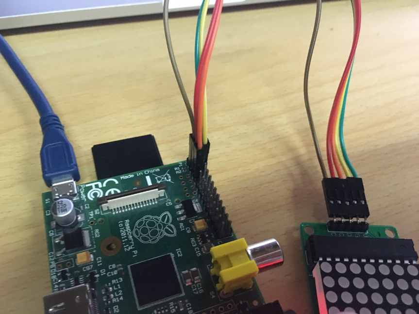
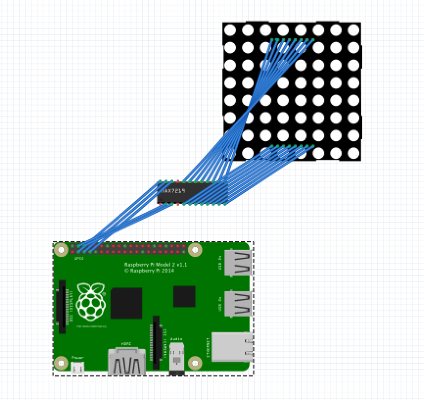
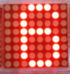
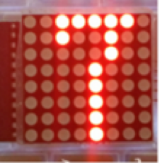
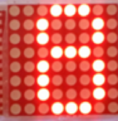
Lab8 网络LED矩阵显示器
实验连接示意图、实物图
所用器材列表
硬件
- Linux实验板卡一块
- 5V/1A电源一个
- microUSB线一根
- 面包板一块
- MAX7219驱动的8*8LED矩阵一个
- 面包线若干
- PC一台
- 以太网线一根
软件
- 编译软件
- Fritzing
外部设备连线图
实验步骤
1. 设计方案,画连线示意图
2. 在面包板上连线,画连线示意图
3. 编写Linux应用程序,能通过第七次实验的设备驱动程序控制LED矩阵显示字符串,每个字符停留500ms
1) 使用ssh连接上Raspberry pi 2
2) 使用insmod将实验七的模块插入
3) 编写C代码,通过设备驱动程序控制LED矩阵显示字符串
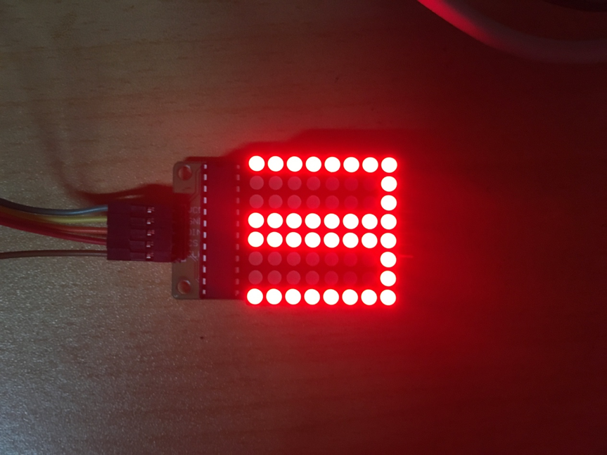
4. 编写Linux应用程序,能通过TCP接受一个连接,将发来的文字在LED矩阵上流动显示出来
5. 用telnet连接linux板卡,发送字符串来显示
1) 使用telnet命令连接Raspberry pi并发送字符串“0123”
2) 观察是否连接成功,板卡上是否接收到发来的字符串
3) 观察点阵能否正常显示
代码和解释
1. 通过实验七的设备驱动程序控制LED矩阵显示字符串
int Matrix;
int main(){
Matrix = open("/dev/matrix", O_WRONLY);
if (Matrix < 0){ // 打开失败
fprintf(stderr, "Cound not open matrix device");
exit(1);
}
write(Matrix, ALLCHAR, strlen(ALLCHAR)); // 写入
return 0;
}
2. 通过TCP接受连接并将发来的字符显示
int Matrix;
int server;
int main(){
// 打开matrix
Matrix = open("/dev/matrix", O_WRONLY);
if (Matrix < 0){
fprintf(stderr, "Cound not open matrix device\n");
exit(1);
}
// 建立服务器
int server = socket(AF_INET, SOCK_STREAM, IPPROTO_TCP);
struct sockaddr_in serverAddr;
serverAddr.sin_family = AF_INET;
serverAddr.sin_addr.s_addr = inet_addr(ADDR);
serverAddr.sin_port = htons(PORT);
// 绑定ip以及端口
if (bind(server, (struct sockaddr*)&serverAddr, sizeof(serverAddr)) == -1){
fprintf(stderr, "Count not bind %s:%d\n", ADDR, PORT);
exit(1);
}
if (listen(server, QUEUE) == -1){
fprintf(stderr, "Listen error\n");
exit(1);
}
printf("Server running at %s:%d\n", ADDR, PORT);
while (1){
struct sockaddr_in clientAddr;
socklen_t length = sizeof(clientAddr);
// 对连入的连接进行处理
int conn = accept(server, (struct sockaddr*)&clientAddr, &length);
if (conn < 0){
fprintf(stderr, "Connect error");
exit(1);
}
printf("A new connection from %s:%d\n", inet_ntoa(clientAddr.sin_addr), clientAddr.sin_port);
// 处理连接发送过来的字符
while (1){
char receiveBuf[BUFF_SIZE];
int count;
memset(receiveBuf, 0, sizeof(receiveBuf));
// 接收字符
count = recv(conn, receiveBuf, sizeof(receiveBuf), 0);
// 如果接收到的字符为空,则表示离开
if (count == 0){
close(conn);
break;
}
// 将接收到的所有字符发送给matrix进行显示
write(Matrix, receiveBuf, count);
}
}
close(server);
return 0;
}
Lab7 字符设备驱动程序
实验连接示意图、实物图

所用器材列表
硬件
- Linux实验板卡一块
- 5V/1A电源一个
- microUSB线一根
- 面包板一块
- MAX7219驱动的8*8LED矩阵一个
- 面包线若干
- PC一台
- 以太网线一根
软件
- 编译软件
- Fritzing
外部设备连线图
实验步骤
1. 设计方案,画连线示意图
2. 在面包板上连线,完成外部电路
3. 编写C/C++程序,采用Arduido-ish库或虚拟文件系统访问GPIO,实现在矩阵上显示文字或图案
1) 使用ssh连接上Raspberry
2) 编写C/C++程序,通过虚拟文件系统控制GPIO
3) 编译并执行C/C++程序,执行结果如下
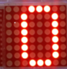
4. 编写字符设备驱动程序,直接访问GPIO控制寄存器,能将write() 送来的单个字符在矩阵上显示出来
1) 编写字符设备驱动的内核模块程序
2) 编译程序并将内核模块插入
3) 使用驱动程序在矩阵上显示数字


代码和解释
1. 利用虚拟文件系统访问GPIO,实现在矩阵上显示文字或图案
1 | GPIO_Pin din, cs, clk; int write_byte(unsigned char b){ unsigned char i, tmp; for (i=0; i<8; i++){ tmp = (b & 0x80) > 0; b <<= 1; GPIO_Pin_Write(&din, tmp); GPIO_Pin_Write(&clk, 1); GPIO_Pin_Write(&clk, 0); } } int write_word(unsigned char addr, unsigned char num){ GPIO_Pin_Write(&cs, 1); GPIO_Pin_Write(&cs, 0); GPIO_Pin_Write(&clk, 0); write_byte(addr); write_byte(num); GPIO_Pin_Write(&cs, 1); } int Matrix_init(){ // 点阵初始化 write_word(0x09, 0x00); // 编码模式 write_word(0x0a, 0x03); // 亮度 write_word(0x0b, 0x07); // 扫描数码管个数 write_word(0x0c, 0x01); // 工作模式 } int Matrix_render(unsigned char* tmp){ // 点阵显示 int i; for (i=0; i<8; i++){ printf("%d %d\n", i, tmp[i]); write_word(i+1, tmp[i]); } } int Matrix_clear(){ // 点阵清屏 unsigned char SCN[]={ 0xFF, 0x01, 0x01, 0xFF, 0xFF, 0x01, 0x01, 0xFF }; Matrix_render(SCN); } int main(){ GPIO_Pin_export(&din, DIN, GPIO_DIRECTION_OUT); GPIO_Pin_export(&cs, CS, GPIO_DIRECTION_OUT); GPIO_Pin_export(&clk, CLK, GPIO_DIRECTION_OUT); Matrix_init(); Matrix_clear(); return 0; } |
2. 字符设备驱动程序
MODULE_LICENSE("GPL");
void write_byte(unsigned char b){
unsigned char i, tmp;
for (i=0; i<8; i++){
tmp = (b & 0x80) > 0;
b <<= 1;
gpio_set_value(DIN, tmp);
gpio_set_value(CLK, 1);
gpio_set_value(CLK, 0);
}
}
void write_word(unsigned char addr, unsigned char num){
gpio_set_value(CLK, 0);
gpio_set_value(CS, 1);
gpio_set_value(CS, 0);
write_byte(addr);
write_byte(num);
gpio_set_value(CS, 1);
}
void Matrix_render(unsigned char* tmp){ // 点阵显示
int i;
for (i=0; i<8; i++){
write_word(i+1, tmp[i]);
}
}
unsigned char digits[][8]={
{0x1c, 0x22, 0x22, 0x22, 0x22, 0x22, 0x22, 0x1c}, // 0
{0x08, 0x18, 0x08, 0x08, 0x08, 0x08, 0x08, 0x1c}, // 1
{0x1c, 0x22, 0x22, 0x04, 0x08, 0x10, 0x20, 0x3e}, // 2
{0x1c, 0x22, 0x02, 0x0c, 0x02, 0x02, 0x22, 0x1c}, // 3
{0x04, 0x0c, 0x14, 0x14, 0x24, 0x1e, 0x04, 0x04}, // 4
{0x3e, 0x20, 0x20, 0x3c, 0x02, 0x02, 0x22, 0x1c}, // 5
{0x1c, 0x22, 0x20, 0x3c, 0x22, 0x22, 0x22, 0x1c}, // 6
{0x3e, 0x24, 0x04, 0x08, 0x08, 0x08, 0x08, 0x08}, // 7
{0x1c, 0x22, 0x22, 0x1c, 0x22, 0x22, 0x22, 0x1c}, // 8
{0x1c, 0x22, 0x22, 0x22, 0x1e, 0x02, 0x22, 0x1c}, // 9
};
unsigned char SCN[]={
0x99, 0x01, 0x01, 0x99, 0x99, 0x01, 0x01, 0x99
};
void Matrix_clear(void){ // 点阵清屏
Matrix_render(SCN);
}
void Matrix_init(void){ // 点阵初始化
write_word(0x09, 0x00); // 编码模式
write_word(0x0a, 0x03); // 亮度
write_word(0x0b, 0x07); // 扫描数码管个数
write_word(0x0c, 0x01); // 工作模式
Matrix_clear();
}
unsigned char disp[BUFFERSIZE];
int head = 0, tail = 0;
static struct timer_list timer;
void Matrix_next_display(unsigned long);
void ptr_inc(int *ptr){
*ptr = (*ptr + 1) % BUFFERSIZE;
}
static void timer_register(struct timer_list* ptimer){
init_timer(ptimer);
ptimer->data = DELAYTIME;
ptimer->expires = jiffies + (DELAYTIME * HZ);
ptimer->function = Matrix_next_display;
add_timer(ptimer);
}
void disp_start(void){
timer_register(&timer);
}
void Matrix_next_display(unsigned long data){
if (head != tail){
unsigned char *ptr = SCN;
unsigned char c = disp[head];
if ('0' <= c && c <= '9'){
ptr = digits[c - '0'];
}
Matrix_render(ptr);
ptr_inc(&head);
disp_start();
}else{
Matrix_clear();
}
}
static int matrix_write(struct file *file, const char __user *buffer,
size_t count, loff_t *ppos){
int i;
if (head == tail && count > 0){
disp_start();
}
for (i=0; i<count; i++){
ptr_inc(&tail);
if (tail == head)
ptr_inc(&head);
disp[tail] = buffer[i];
}
return count;
}
static struct file_operations matrix_fops = {
.owner = THIS_MODULE,
.write = matrix_write,
.llseek = noop_llseek
};
static struct miscdevice matrix_misc_device = {
.minor = MISC_DYNAMIC_MINOR,
.name = "matrix",
.fops = &matrix_fops
};
static int __init matrix_init(void){
if (!gpio_is_valid(DIN) || !gpio_is_valid(CLK) || !gpio_is_valid(CS)){
printk(KERN_INFO "GPIO_TEST: invalid GPIO\n");
return -ENODEV;
}
misc_register(&matrix_misc_device);
gpio_request(DIN, "sysfs");
gpio_direction_output(DIN, 0);
gpio_request(CS, "sysfs");
gpio_direction_output(CS, 1);
gpio_request(CLK, "sysfs");
gpio_direction_output(CLK, 0);
Matrix_init();
printk(KERN_INFO"matrix device has been registed.\n");
return 0;
}
static void __exit matrix_exit(void){
misc_deregister(&matrix_misc_device);
printk(KERN_INFO"matrix device has been unregisted.\n");
del_timer(&timer);
}
module_init(matrix_init);
module_exit(matrix_exit);
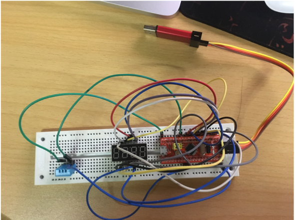
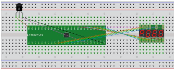
Lab5 uC/OS 室温计
实验连接示意图
所用器材列表
硬件
- STM32F103核心板一块
- USB串口板一块
- 面包板一块
- 两位7段数码管(共阳)一颗
- 360Ω 1/8W电阻2颗
- DHT-11温湿度传感器1个
- 面包线若干
软件
- 编译软件
- Fritzing
外部设备连线图
实验步骤、操作的命令和结果
1.设计输出方案,画连线示意图
2.在面包板上连线,完成外部电路
3.编写C/C++程序,测试程序和电路
1) 测试、实现uC/OS对GPIO的访问
2) 实现DHT-11数据的读
3) 实现以时分复用方式在四位7段数码管上一次显示0000-9999的数字
4) 用两个uC/OS任务,一个定时读DHT-11数据,一个轮询驱动数码管,一秒一次显示当前湿度和温度。注意处理好两个任务之间的数据共享
源代码
7段数码管程序
1 | void GPIO_Configuration(void) { |
DHT11数据读取及显示
1 |
|
Lab6 Linux系统调用
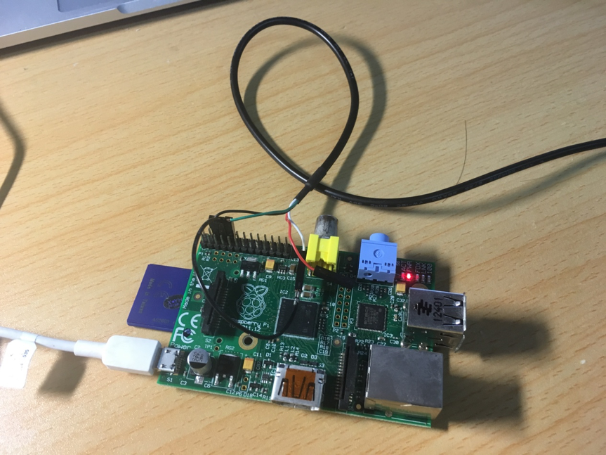
实验连接示意图
所用器材列表
硬件
- Raspberry Pi2板一块
- 5V/1A电源一个
- microUSB线一根
- PC一台
软件
- 内核源码
实验步骤
1. 寻找、下载Linux实验版本所用的Linux内核源码

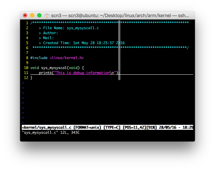
2. 在内核中加入新的系统调用,输出调试信息
a) 在arch/arm/kernel下新建一个sys_mysyscall.c文件,内容如下

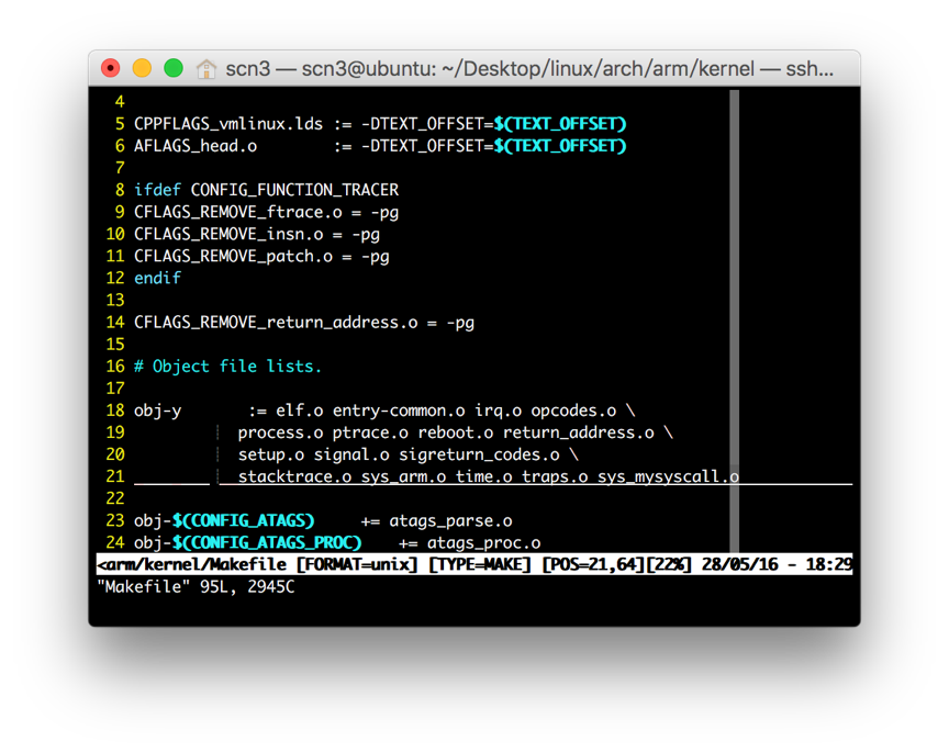
b) 修改Makefile,增加sys_mysyscall.o到obj-y末尾
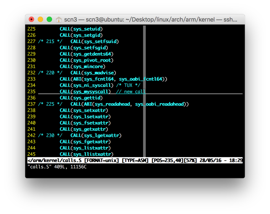
c) 修改arch/arm/kernel/call.S中的223号调用
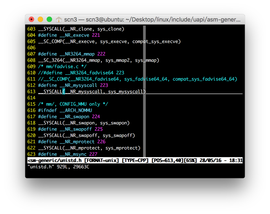
d) 修改include/uapi/asm-generic/unistd.h中的223号调用
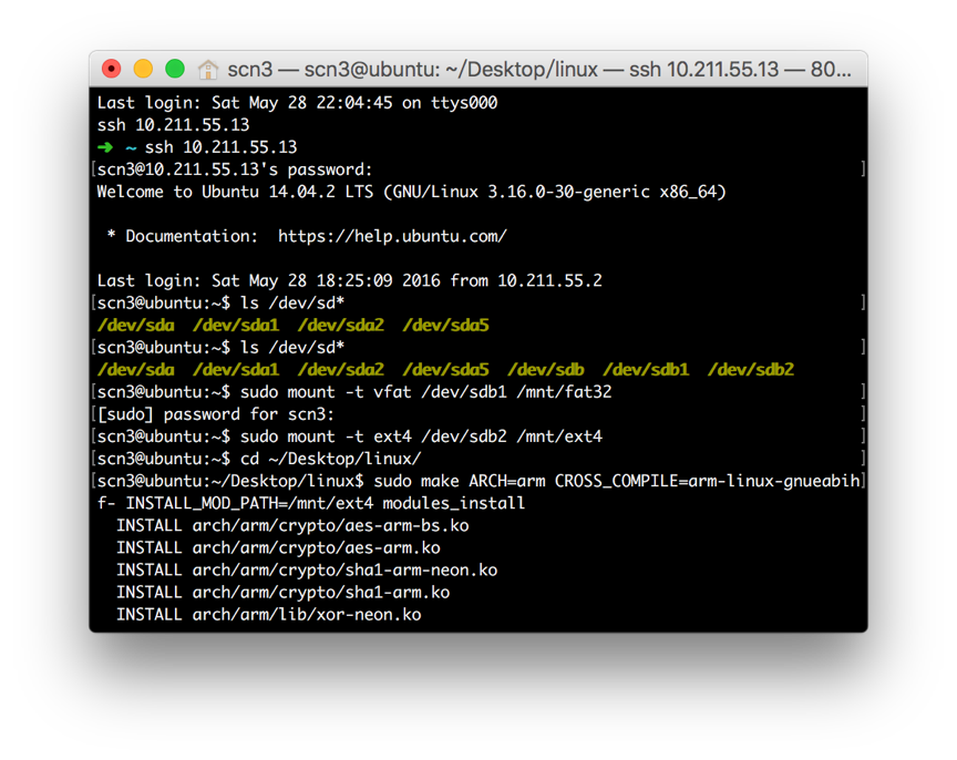
3. 修改内核代码配置,编译内核
a) 输入配置命令
KERNEL=kernel7
make ARCH =arm CROSS_COMPILE=arm-linux-gnueabihf- bcm2709_defconfig
b) 输入编译命令
make ARCH=arm CROSS_COMPILE=arm-linux-gnueabihf- zImage modules dtbs -j4
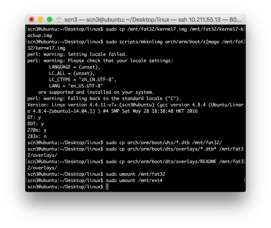
4. 将编译好的内核装载到板卡启动
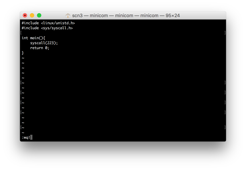
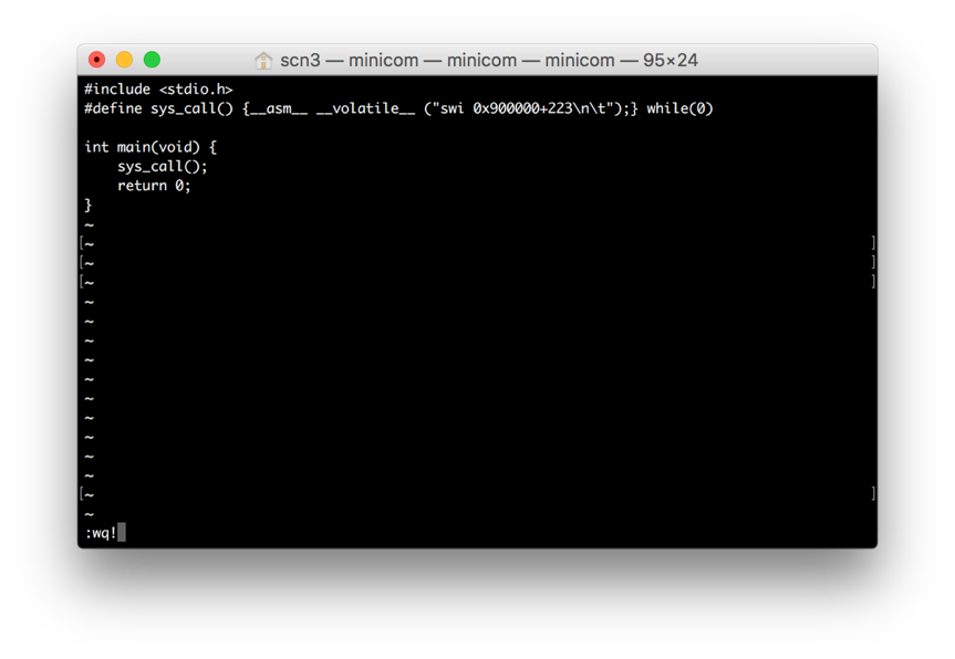
5. 编写C代码,用两种方法做系统调用,测试
- 嵌入汇编代码

- 用syscall()函数
编译并运行后执行dmesg | tail -5
6. 编写内核模块,在模块加载和卸载时能通过内核打印函数输出提示信息
内核模块: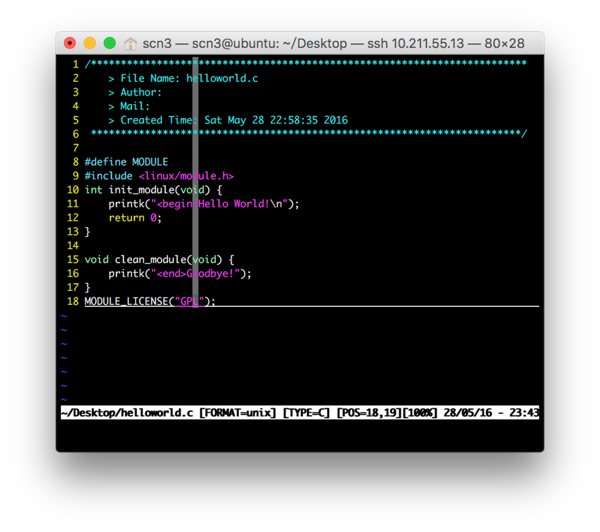
7. 通过insmod和lsmod等命令测试内核模块
系统调用代码和修改内核的地方
1. 系统调用代码
2. 内核修改
- arch/arm/kernel/call.S

- include/uapi/asm-generic/unistd.h

测试用的代码和结果
1. 测试系统调用的用户代码

2. 测试内核模块:使用lsmod和dmesg | tail -5命令

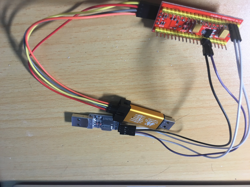
Lab4 bootloader
实验连接示意图
所用器材列表
硬件
- STM32F103核心板一块
- microUSB线
- STLinkban板和USB串口板
软件
- 交叉编译软件
实验步骤、操作的命令和结果
连接STM32和其他设备
写一个自己的建议bootloader,能通过串口执行两条最简单的指令:
1 | // 串口输出单个字符 void myPutc(char ch) { HAL_UART_Transmit(&huart1,(uint8_t*)&ch,1,100); } // 串口输出字符串 void myPuts(char *str) { for (int i = 0; i < strlen(str); i++) myPutc(str[i]); } // 串口读取单个字符(时限time_bound) int8_t myGetc(uint8_t *c, uint16_t time_bound) { while (time_bound) { // 时限控制 if (uart_rev.front != uart_rev.rear) { *c = *uart_rev.front; uart_rev.front++; if (uart_rev.front >= buf + BUFSIZE) // 下标控制 uart_rev.front = buf; return 0; } time_bound--; } return (int8_t) – 1; } // 串口读取字符串 int8_t myGets(uint8_t *str, uint16_t bound) { int count = 0; bound--; while (count < bound) { if (uart_rev.front != uart_rev.rear) { char ch = *uart_rev.front; uart_rev.front++; if (uart_rev.front > buf + BUFSIZE) uart_rev.front = buf; if (ch == '\r') // 处理换行 break; *str = ch; if (ch != ' ') { // 非空有效 str++; count++; } } } *str = '\0'; return count; } |
中断处理
1 | void HAL_UART_RxCpltCallback(UART_HandleTypeDef *UartHandle) { uint8_t ret = HAL_OK; char ch = *uart_rev.rear; myPutc(ch); if (c == '\r') // 回车补’\n’ myPutc('\n'); // 移动buf指针 uart_rev.rear++; if (uart_rev.rear > buf + BUFSIZE) uart_rev.rear = buf; if (uart_rev.rear == uart_rev.front) { uart_rev.front++; if (uart_rev.front > buf + BUFSIZE) uart_rev.front = buf; } do{ }while(HAL_UART_Receive_IT(UartHandle, uart_rev.rear, 1) != HAL_OK); } void USART1_IRQHandler(void){ //调用HAL函数库自带的处理函数 HAL_UART_IRQHandler(&huart1); } |
命令处理
while (1) {
  char cmd[MAXLEN];
  char s2[MAXLEN];
  count = 0;
  myPuts("Please input your instruction: ");
  count = myGets((uint8_t*)s1, MAXLEN); // 获取输入
  sscanf(s1, "%s", cmd);
  if (strcmp(cmd, "peek") == 0) { // “peek”命令
int addr;
int res = sscanf(s1 + PEEKLEN, “%x %s”, &addr, s2);
if (res == 1) {
  sprintf(s2, "peek: %x %x\r\n, addr, *((int *)addr)");
  myPuts(s2);  // 输出结果
}
else myPuts("error\r\n");
  }
  else if (strcmp(cmd, "poke") == 0) {
int addr, data;
int res = sscanf(str + POKELEN, "%x %x %s", &addr, &data, s);
if (res == 2) {
  *((int *)addr) = data; // 写入数据
  sprintf(s2, "poke: %x %x\r\n", addr, *((int *)addr));
  myPuts(s2);
}
else myPuts("error\r\n");  // 出错
  }
           else myPuts("error\r\n");   // 非peek或poke命令
}
结果与分析
poke命令执行完之后,peek对应地址能得到正确的数据,符合实验预期。
Lab3 自行车码表
实验连接示意图
整体图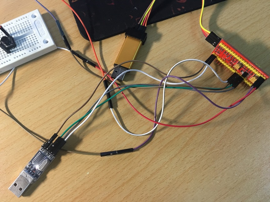
STM32和USB连接图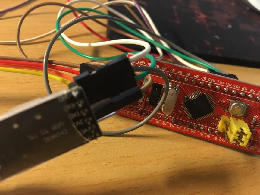
STM32和STLink连接图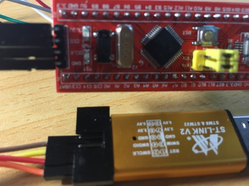
面包板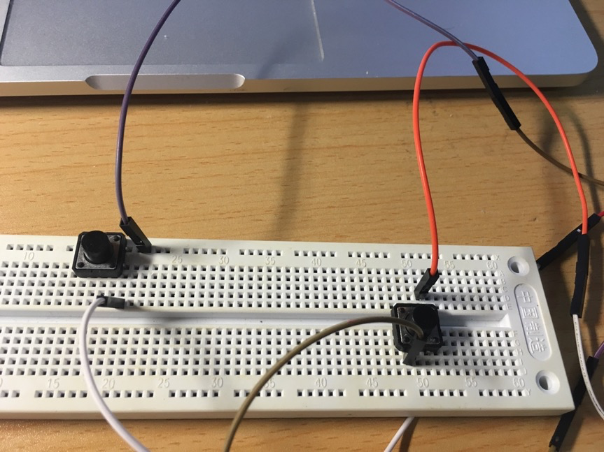
实验步骤
- 连接STM32和其他设备,并下载安装mdk等所需软件。
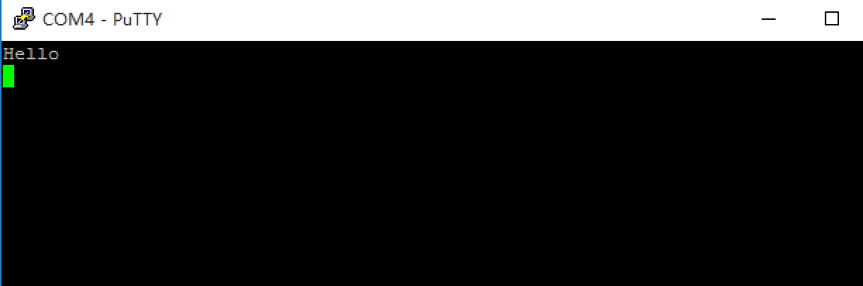
- 编写Cube程序,配置UART0为9600,8n1,上电后向串口输出“Hello”,在PC上通过串口软件观察结果。结果如下:
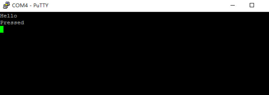
- 编写Cube程序,配置PA11和PA12为内部上拉到输入模式,在main()函数循环检测PA11按钮按下,并在按钮按下时在串口输出“Pressed”。结果如下:
- 编写Cube程序,配置PA12下降沿触发中断,程序中设置两个全局变量,一个为计数器,一个为标识。当中断触发时,计数器加1,并设置标识。在主循环中判断标识,如果标识置位则清除标识并通过串口输出计数值。结果如下,当PA12按下时,count加1并显示。

- 编写Cube程序,开启定时器为200ms中断一次,中断触发时设置标识,主循环根据这个标识在做串口输出(取消4的串口输出)。结果如下,定时输出count。

- 编写完成的码表程序,PA12的按钮标识车轮转了一圈,通过计数器可以得到里程,通过定时器中断得到的时间可以计算出速度;PA11的按钮切换模式,模式一在串口输出里程,模式二在串口输出速度。具体显示结果见“四、结果与分析”
源代码
main.c
1 |
|
stm32f1xx_hal_msp.c
1 | void HAL_MspInit(void) { __HAL_RCC_AFIO_CLK_ENABLE(); HAL_NVIC_SetPriorityGrouping(NVIC_PRIORITYGROUP_4); /* System interrupt init*/ /* SysTick_IRQn interrupt configuration */ HAL_NVIC_SetPriority(SysTick_IRQn, 0, 0); /**DISABLE: JTAG-DP Disabled and SW-DP Disabled */ } // 初始化 void HAL_UART_MspInit(UART_HandleTypeDef *huart) { __HAL_RCC_GPIOA_CLK_ENABLE(); __HAL_RCC_USART1_CLK_ENABLE(); GPIO_InitTypeDef GPIO_InitStruct; GPIO_InitStruct.Pin = GPIO_PIN_9; GPIO_InitStruct.Mode = GPIO_MODE_AF_PP; GPIO_InitStruct.Speed = GPIO_SPEED_HIGH; HAL_GPIO_Init(GPIOA, &GPIO_InitStruct); GPIO_InitStruct.Pin = GPIO_PIN_10; HAL_GPIO_Init(GPIOA, &GPIO_InitStruct); } // 善后 void HAL_UART_MspDeInit(UART_HandleTypeDef *huart) { __HAL_RCC_USART1_FORCE_RESET(); __HAL_RCC_USART1_RELEASE_RESET(); HAL_GPIO_DeInit(GPIOA, GPIO_PIN_9); HAL_GPIO_DeInit(GPIOA, GPIO_PIN_10); } // 初始化 void HAL_TIM_Base_MspInit(TIM_HandleTypeDef* htim_base) { if(htim_base->Instance==TIM3) { __TIM3_CLK_ENABLE(); HAL_NVIC_SetPriority(TIM3_IRQn, 0, 0); HAL_NVIC_EnableIRQ(TIM3_IRQn); } } // 善后 void HAL_TIM_Base_MspDeInit(TIM_HandleTypeDef* htim_base) { if(htim_base->Instance==TIM3) { __TIM3_CLK_DISABLE(); HAL_NVIC_DisableIRQ(TIM3_IRQn); } } |
结果与分析
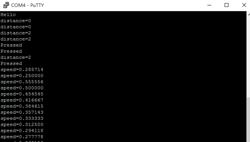
如上图,是自行车码表的运行结果。当按下STM32上的reset时,码表被重启,并向串口发送“Hello”。启动后默认在模式一下运行,根据定时器输出里程,按当下P11时切换模式,在模式二下运行并根据定时器输出速度,符合实验预期。但由于未对按键进行去抖,可能会出现像第一次那样按下一次PA11却连续出现两次“Pressed”的情况。
Lab2 ARM指令
实际连接示意图
仅一台macbook pro
所用器材列表
macbook一台
各项测试情况
- 生成了Thumb指令还是ARM指令
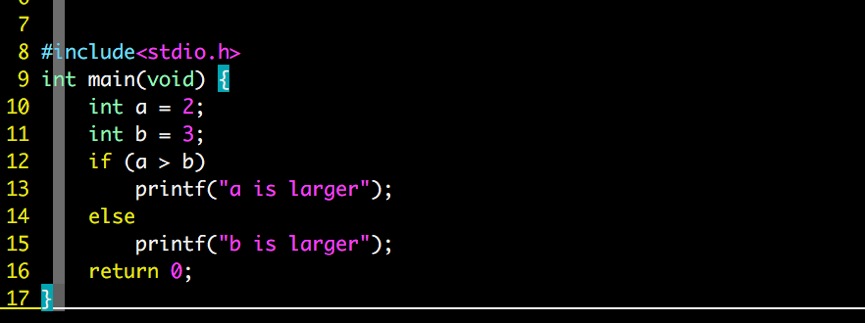
- C代码
- 通过编译参数改成,使得其编译成ARM指令或thumb指令
默认为ARM指令
加上参数-mthumb编译为thumb指令
- 汇编代码情况
用arm-linux-gnueabi-objdump –d 命令查看汇编码
ARM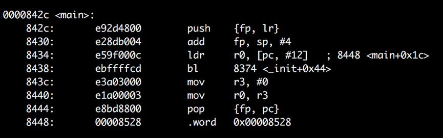
thumb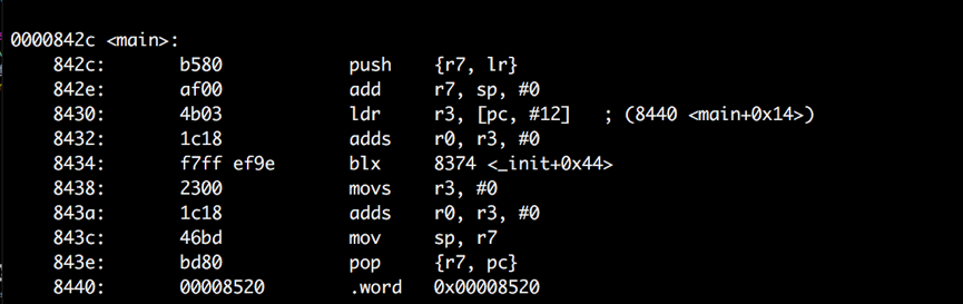
对比上述汇编可知,ARM和Thumb编译的结果最大的不同是32位与16位的区别,且Thumb的指令数比ARM多,但整体上,ARM汇编结果比Thumb的大(ls –l的结果如下)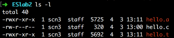
- C代码
- 对于ARM指令,能否产生条件执行的指令
- C代码
- ARM指令
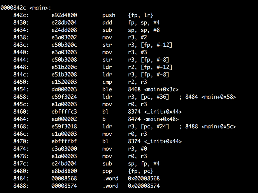
观察8454的ble可知,能产生条件执行的指令。
- C代码
- 设计C的代码场景,观察是否产生了寄存器移位寻址
- C代码
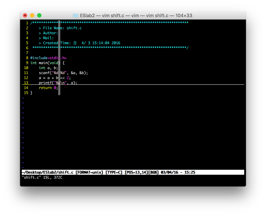
- 在编译参数中加入-O开启优化:

- ARM指令
观察84a4可知,产生了寄存器移位寻址。
- C代码
- 设计C的代码场景,观察一个复杂的32位数是如何装载到寄存器的
- C代码
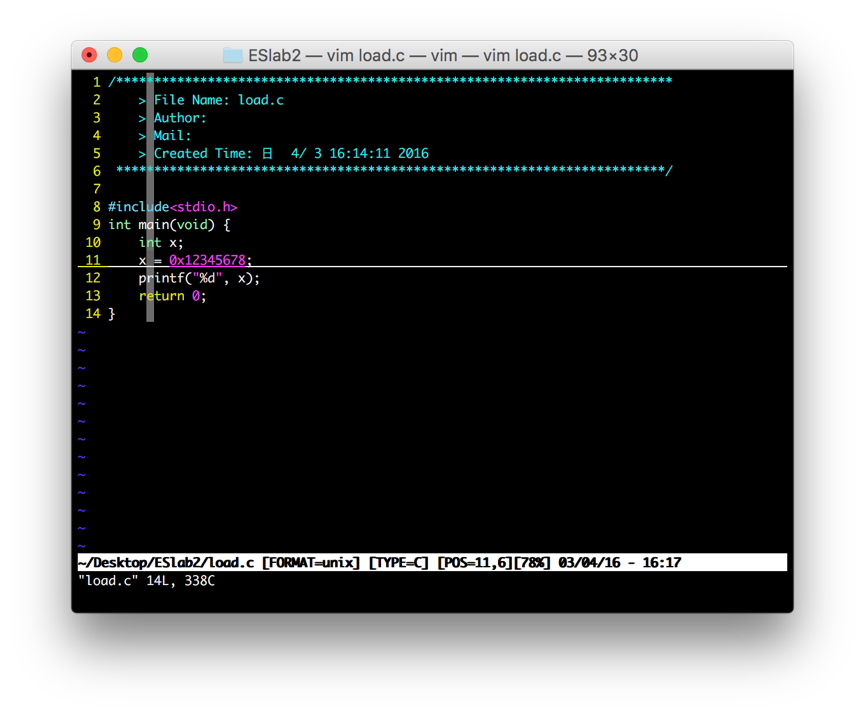
- ARM指令
观察可知,32位数先被存在了8460处,然后用ldr指令将之装入寄存器r3
- C代码
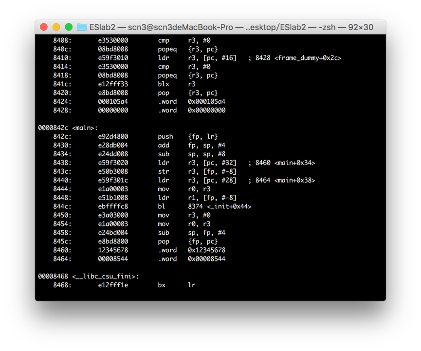
- 写一个C的多重函数调用的函数,观察并分析
- C代码
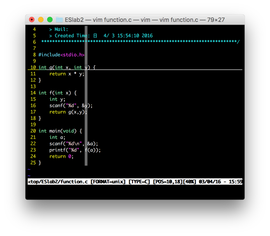
- ARM指令
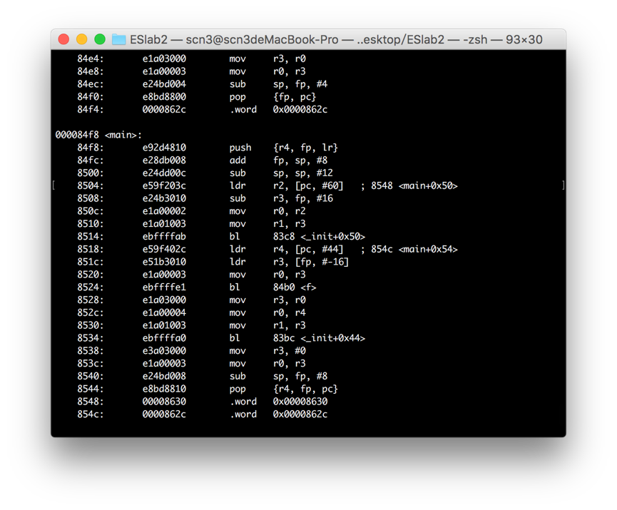
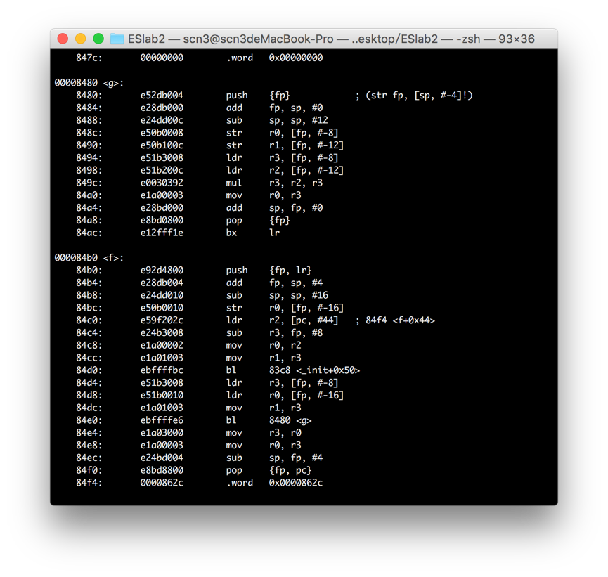
观察和分析可知:
a) 调用时的返回地址在lr链接寄存器中,在执行bl指令时,会自动将下一条指令地址传入lr寄存器。
b) 传入的参数在r0和r1中。
c) 在函数堆栈中,本地变量存在返回地址和fp之后。
d) r0-r3是caller保存而r4是callee保存。
- C代码
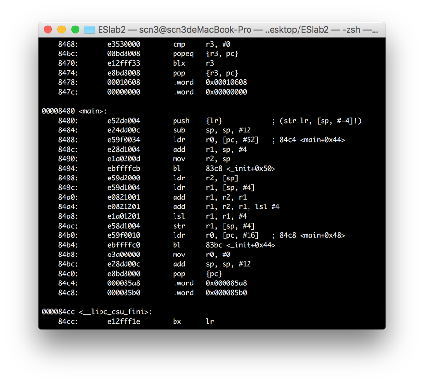
- 尝试写C的表达式来编译得到MLA指令
- C代码
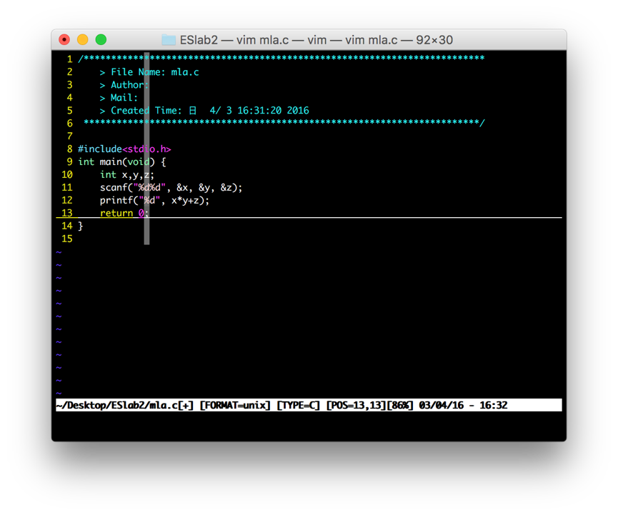
- ARM指令(编译参数加上-O)
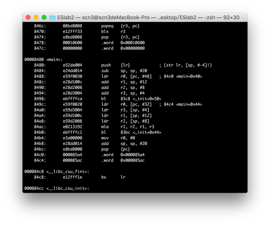
在84ac处出现了mla。
- C代码
- 尝试写C的表达式来编译得到BIC指令
- C代码
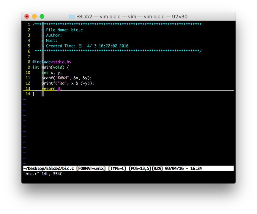
- ARM指令(编译参数加上-O)
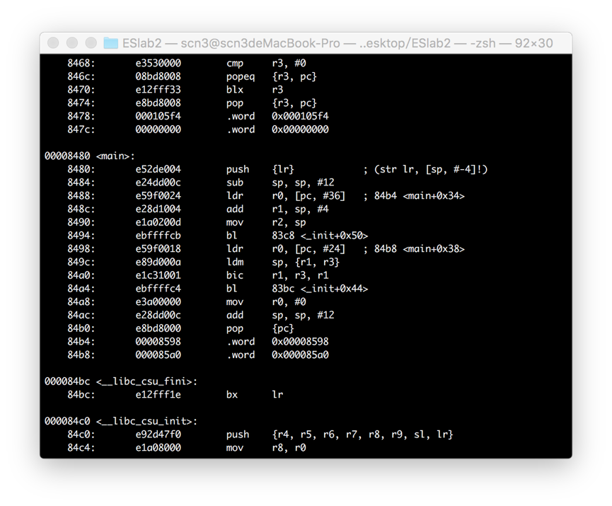
在84a0处出现了bic指令。
- C代码
- 编写一个汇编函数,接受一个整数和一个指针做为输入,指针所指应为一个字符串,该汇编函数调用C语言的 printf()函数输出这个字符串的前n个字符,n即为那个整数。在C语言写的main()函数中调用并传递参数给这个汇编函数 来得到输出。
- 代码如下(用“puts”输出字符串)
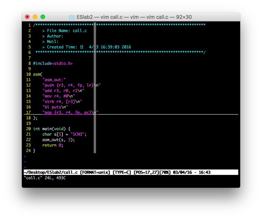
- 代码如下(用“puts”输出字符串)
Lab 1 启动
install Raspbian OS for Raspberry Pi
Download an img file from https://www.raspberrypi.org/downloads
Insert SD card and write the img file to the card.
We can use terminal and enter instructions as follows: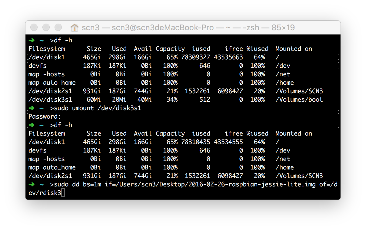
Notice: If your failed to write to your SD card with “dd” instruction, please check if you have permission to write to your SD card. If your permission is only reading, your can insert your SD card violently. More approaches to solve it: http://bbs.feng.com/read-htm-tid-3495425.html
Connect to Raspberry Pi with serial port
- The Serial Port on Raspberry Pi is shown as following:
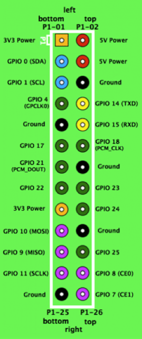
We can connect it as following(While – TXD; Green – RXD; Black – GND):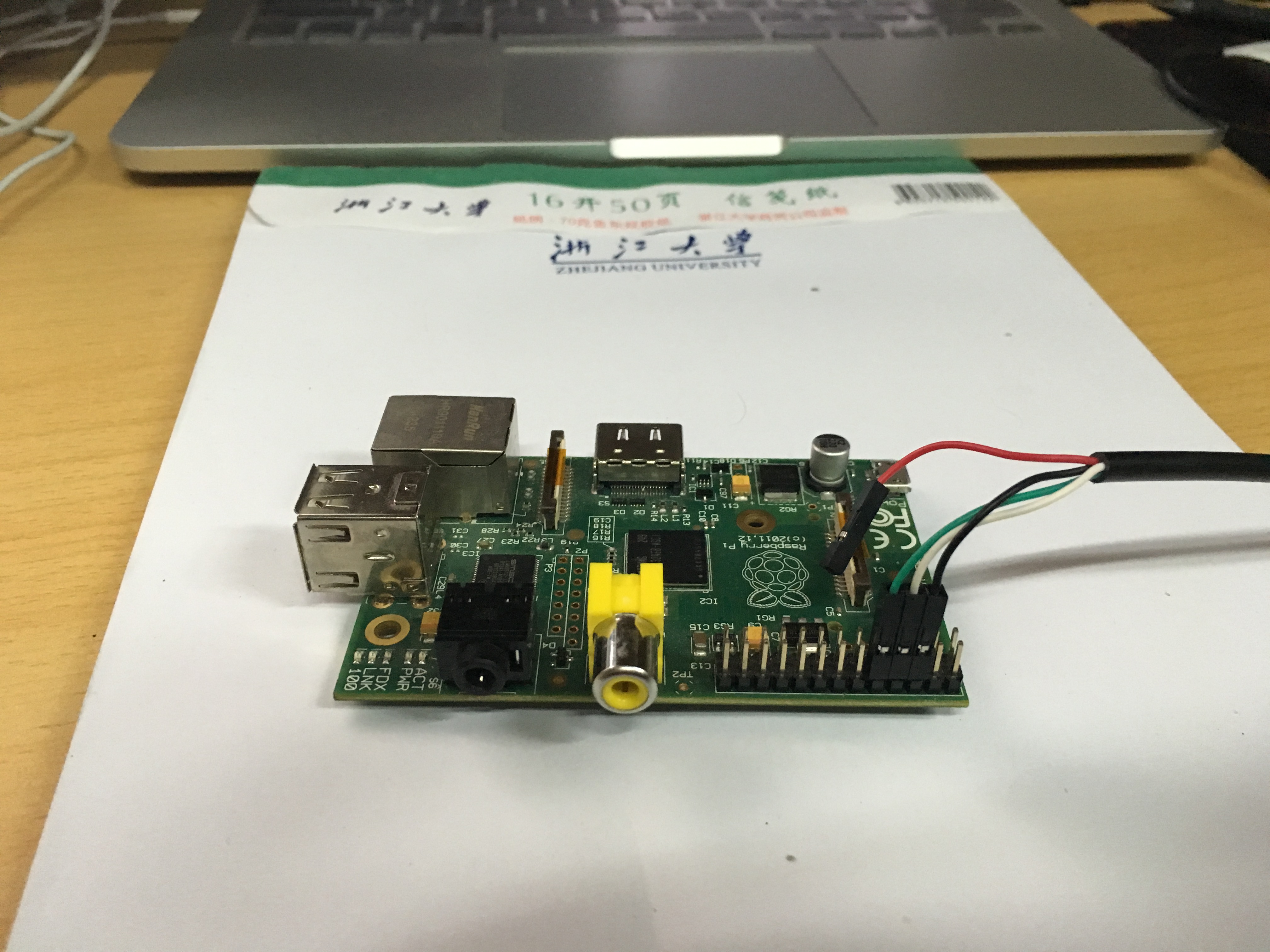
Install a serial driver if you haven’t installed one. (downloaded from http://www.prolific.com.tw/)
Find your serial port and install “screen” if it hasn’t been installed.1
2ls /dev/tty.*
brew install screenConnect to your Raspberry
1
screen /dev/tty.usbserial 115200
Then you can see the infomation about booting of Raspberry as following: 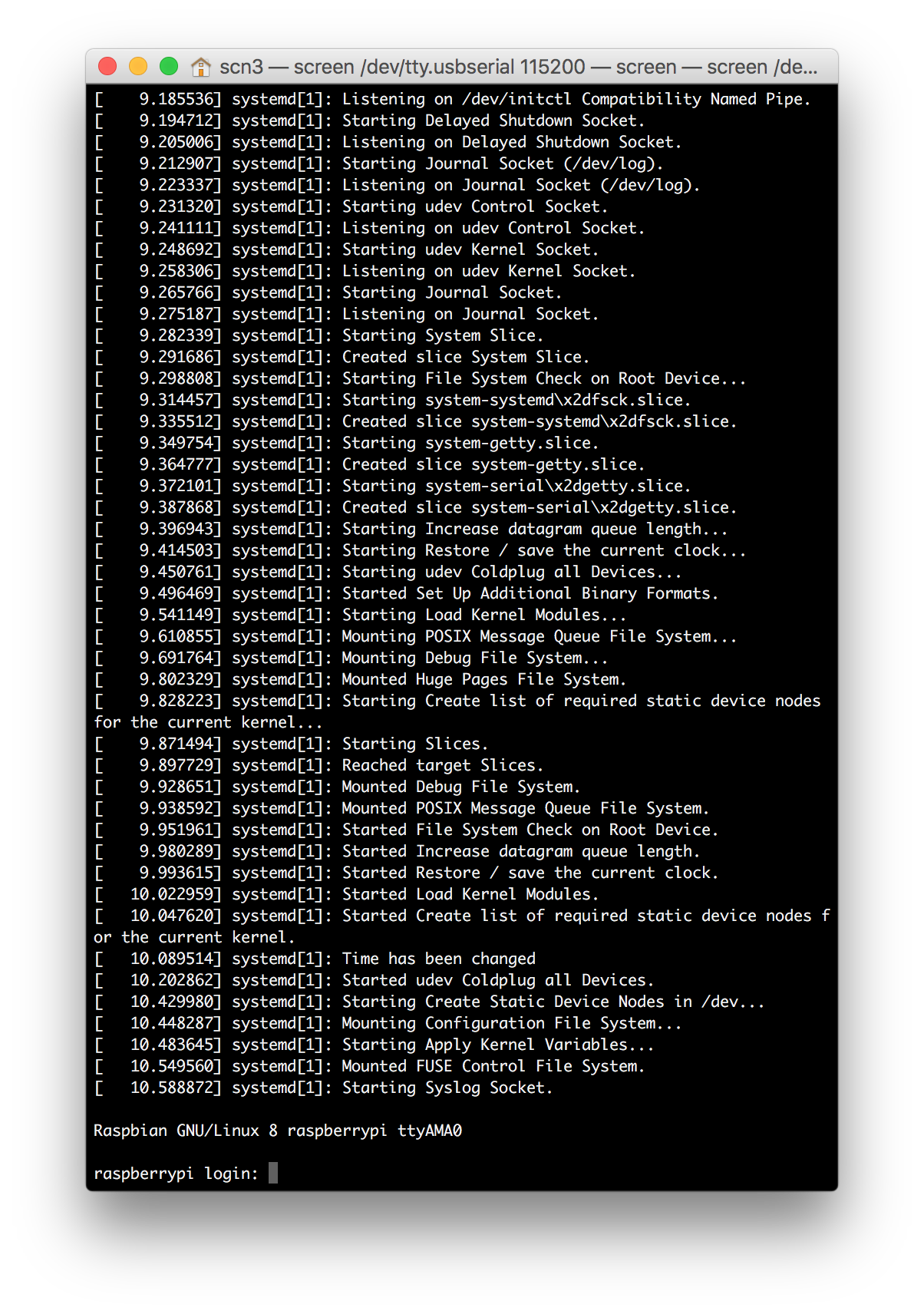
Connect to Raspberry Pi with LAN
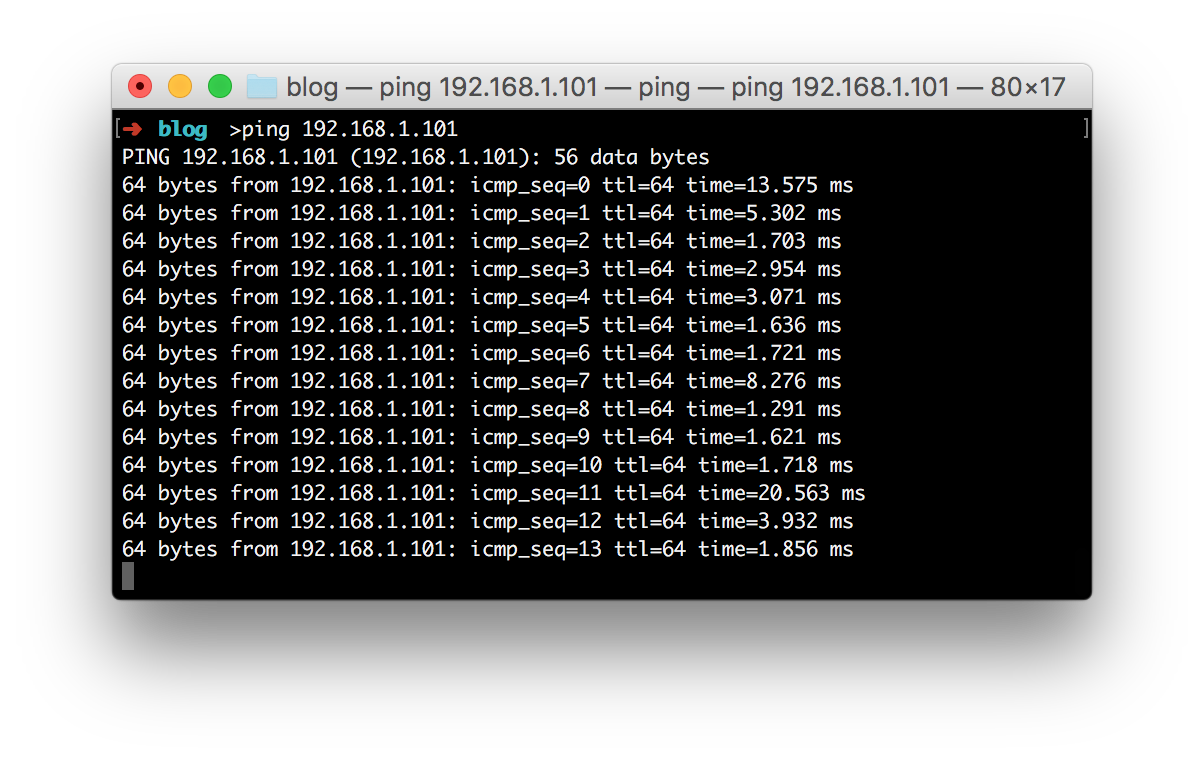
- Connect Raspberry Pi to router with cable and connect your Macbook to corresponding LAN.
- Test connection on Mac
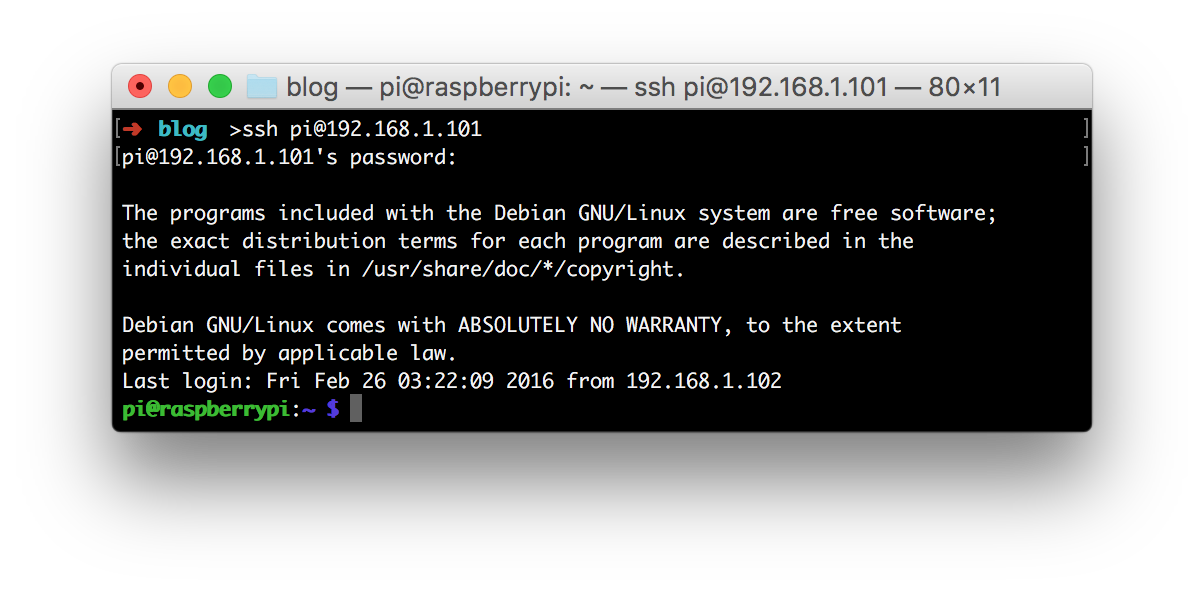
- Connect to Raspberry
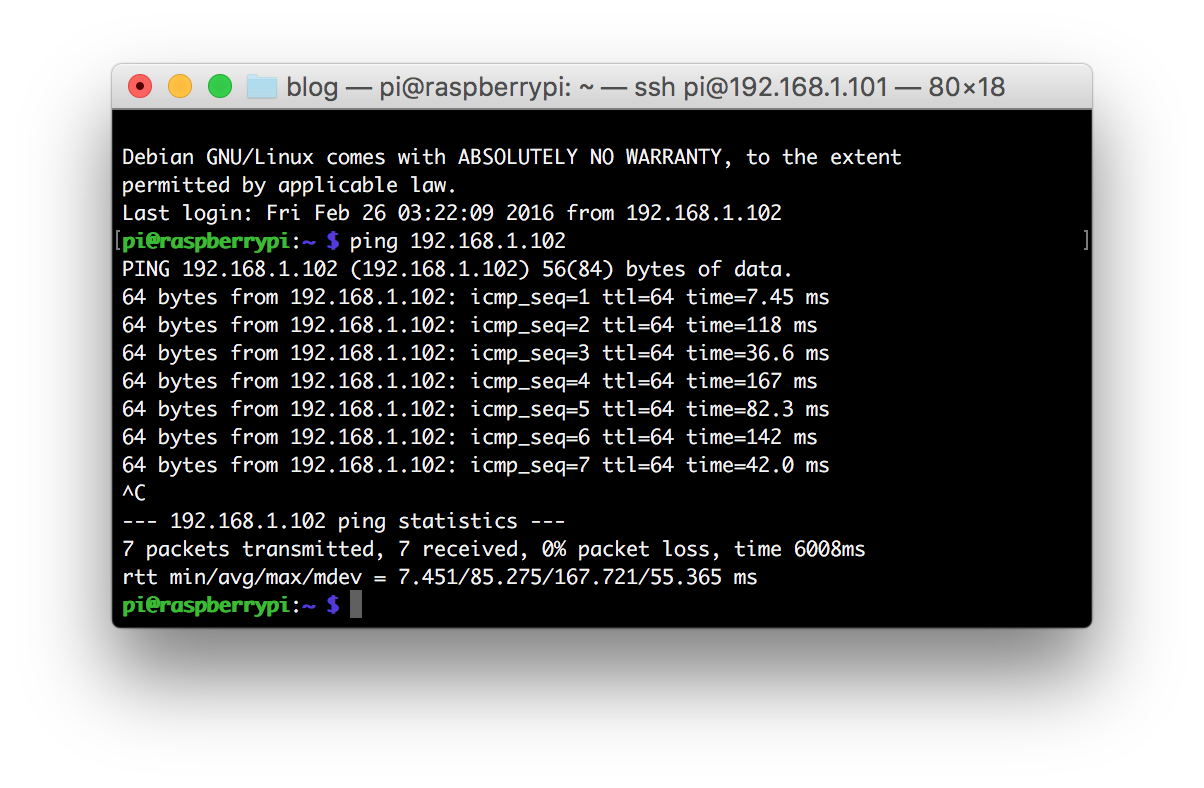
- Test connection on Raspbian
Cross compiling(on Ubuntu)
Install compiler
1
apt-get install gcc-arm-linux-gnueabi make ncurses-dev
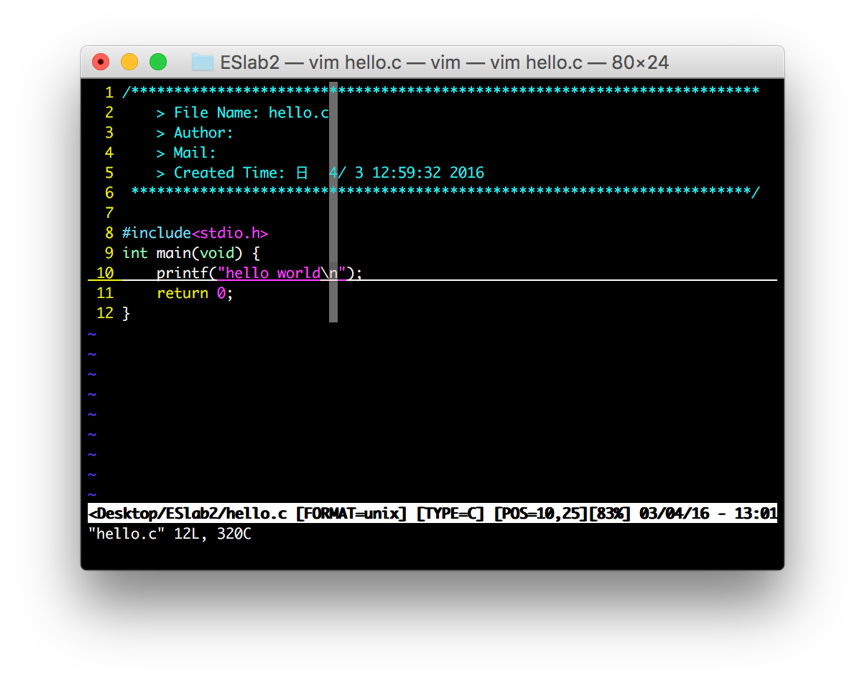
Write program
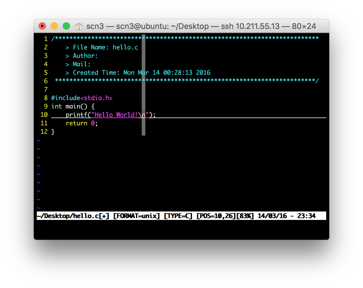
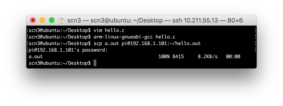
Compile
1
arm-linux-gnueabi-gcc hello.c
Send it to Raspberry
1
scp a.out pi@192.168.1.101:~/hello.out
5.Run the program on Raspberry Pi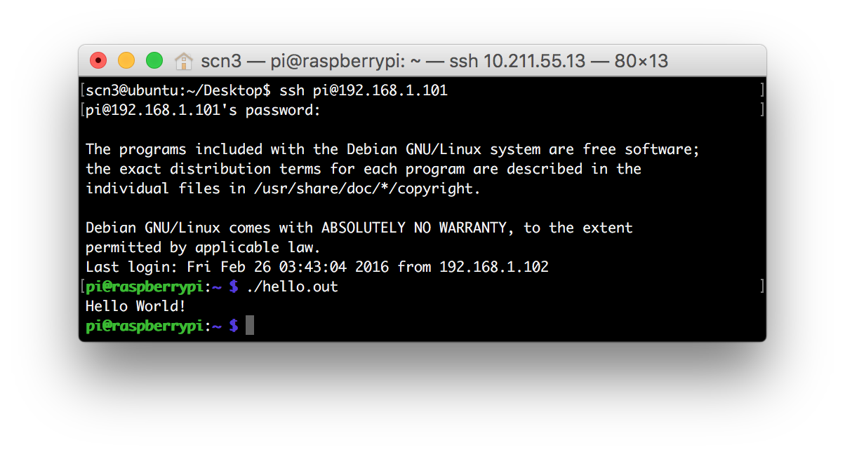
Successfully!
Booting content
Uncompressing Linux… done, booting the kernel.
[ 0.000000] Booting Linux on physical CPU 0x0
[ 0.000000] Initializing cgroup subsys cpuset
[ 0.000000] Initializing cgroup subsys cpu
[ 0.000000] Initializing cgroup subsys cpuacct
[ 0.000000] Linux version 4.1.18+ (dc4@dc4-XPS13-9333) (gcc version 4.9.3 (c6
[ 0.000000] CPU: ARMv6-compatible processor [410fb767] revision 7 (ARMv7), cd
[ 0.000000] CPU: PIPT / VIPT nonaliasing data cache, VIPT nonaliasing instrue
[ 0.000000] Machine model: Raspberry Pi Model B Rev 2
[ 0.000000] cma: Reserved 8 MiB at 0x1b400000
[ 0.000000] Memory policy: Data cache writeback
[ 0.000000] Built 1 zonelists in Zone order, mobility grouping on. Total pa0
[ 0.000000] Kernel command line: dma.dmachans=0x7f35 bcm2708_fb.fbwidth=656 t
[ 0.000000] PID hash table entries: 2048 (order: 1, 8192 bytes)
[ 0.000000] Dentry cache hash table entries: 65536 (order: 6, 262144 bytes)
[ 0.000000] Inode-cache hash table entries: 32768 (order: 5, 131072 bytes)
[ 0.000000] Memory: 436836K/458752K available (5792K kernel code, 488K rwdat)
[ 0.000000] Virtual kernel memory layout:
[ 0.000000] vector : 0xffff0000 - 0xffff1000 ( 4 kB)
[ 0.000000] fixmap : 0xffc00000 - 0xfff00000 (3072 kB)
[ 0.000000] vmalloc : 0xdc800000 - 0xff000000 ( 552 MB)
[ 0.000000] lowmem : 0xc0000000 - 0xdc000000 ( 448 MB)
[ 0.000000] modules : 0xbf000000 - 0xc0000000 ( 16 MB)
[ 0.000000] .text : 0xc0008000 - 0xc076f1f0 (7581 kB)
[ 0.000000] .init : 0xc0770000 - 0xc07c8000 ( 352 kB)
[ 0.000000] .data : 0xc07c8000 - 0xc0842260 ( 489 kB)
[ 0.000000] .bss : 0xc0842260 - 0xc08f63e0 ( 721 kB)
[ 0.000000] SLUB: HWalign=32, Order=0-3, MinObjects=0, CPUs=1, Nodes=1
[ 0.000000] NR_IRQS:522
[ 0.000000] clocksource stc: mask: 0xffffffff max_cycles: 0xffffffff, max_ids
[ 0.000016] sched_clock: 32 bits at 1000kHz, resolution 1000ns, wraps every s
[ 0.000057] Switching to timer-based delay loop, resolution 1000ns
[ 0.000345] Console: colour dummy device 80x30
[ 0.001272] console [tty1] enabled
[ 0.001329] Calibrating delay loop (skipped), value calculated using timer f)
[ 0.001415] pid_max: default: 32768 minimum: 301
[ 0.001796] Mount-cache hash table entries: 1024 (order: 0, 4096 bytes)
[ 0.001867] Mountpoint-cache hash table entries: 1024 (order: 0, 4096 bytes)
[ 0.002923] Initializing cgroup subsys blkio
[ 0.003017] Initializing cgroup subsys memory
[ 0.003086] Initializing cgroup subsys devices
[ 0.003151] Initializing cgroup subsys freezer
[ 0.003212] Initializing cgroup subsys net_cls
[ 0.003329] CPU: Testing write buffer coherency: ok
[ 0.003449] ftrace: allocating 19747 entries in 58 pages
[ 0.107987] Setting up static identity map for 0x81c0 - 0x81f8
[ 0.110179] devtmpfs: initialized
[ 0.121007] VFP support v0.3: implementor 41 architecture 1 part 20 variant 5
[ 0.121462] clocksource jiffies: mask: 0xffffffff max_cycles: 0xffffffff, mas
[ 0.123475] pinctrl core: initialized pinctrl subsystem
[ 0.124379] NET: Registered protocol family 16
[ 0.129874] DMA: preallocated 4096 KiB pool for atomic coherent allocations
[ 0.131376] bcm2708.uart_clock = 3000000
[ 0.136262] hw-breakpoint: found 6 breakpoint and 1 watchpoint registers.
[ 0.136341] hw-breakpoint: maximum watchpoint size is 4 bytes.
[ 0.136549] Serial: AMBA PL011 UART driver
[ 0.136851] 20201000.uart: ttyAMA0 at MMIO 0x20201000 (irq = 83, base_baud =2
[ 0.504867] console [ttyAMA0] enabled
[ 0.509270] bcm2835-mbox 2000b880.mailbox: mailbox enabled
[ 0.555239] bcm2708-dmaengine 20007000.dma: DMA legacy API manager at f200705
[ 0.563970] bcm2708-dmaengine 20007000.dma: Initialized 7 DMA channels (+ 1 )
[ 0.572537] bcm2708-dmaengine 20007000.dma: Load BCM2835 DMA engine driver
[ 0.579467] bcm2708-dmaengine 20007000.dma: dma_debug:0
[ 0.585617] SCSI subsystem initialized
[ 0.589781] usbcore: registered new interface driver usbfs
[ 0.595503] usbcore: registered new interface driver hub
[ 0.601035] usbcore: registered new device driver usb
[ 0.607059] raspberrypi-firmware soc:firmware: Attached to firmware from 2015
[ 0.642750] Switched to clocksource stc
[ 0.695940] FS-Cache: Loaded
[ 0.699246] CacheFiles: Loaded
[ 0.718043] NET: Registered protocol family 2
[ 0.723981] TCP established hash table entries: 4096 (order: 2, 16384 bytes)
[ 0.731171] TCP bind hash table entries: 4096 (order: 2, 16384 bytes)
[ 0.737806] TCP: Hash tables configured (established 4096 bind 4096)
[ 0.744448] UDP hash table entries: 256 (order: 0, 4096 bytes)
[ 0.750345] UDP-Lite hash table entries: 256 (order: 0, 4096 bytes)
[ 0.757037] NET: Registered protocol family 1
[ 0.762009] RPC: Registered named UNIX socket transport module.
[ 0.768067] RPC: Registered udp transport module.
[ 0.772841] RPC: Registered tcp transport module.
[ 0.777576] RPC: Registered tcp NFSv4.1 backchannel transport module.
[ 0.785293] hw perfevents: enabled with armv6_1176 PMU driver, 3 counters ave
[ 0.794424] futex hash table entries: 256 (order: -1, 3072 bytes)
[ 0.816876] VFS: Disk quotas dquot_6.6.0
[ 0.821259] VFS: Dquot-cache hash table entries: 1024 (order 0, 4096 bytes)
[ 0.830944] FS-Cache: Netfs ‘nfs’ registered for caching
[ 0.837706] NFS: Registering the id_resolver key type
[ 0.843012] Key type id_resolver registered
[ 0.847236] Key type id_legacy registered
[ 0.855071] Block layer SCSI generic (bsg) driver version 0.4 loaded (major )
[ 0.863073] io scheduler noop registered
[ 0.867075] io scheduler deadline registered (default)
[ 0.872649] io scheduler cfq registered
[ 0.879094] BCM2708FB: allocated DMA memory 5b800000
[ 0.884268] BCM2708FB: allocated DMA channel 0 @ f2007000
[ 0.894833] Console: switching to colour frame buffer device 82x26
[ 0.906093] Serial: 8250/16550 driver, 0 ports, IRQ sharing disabled
[ 0.915871] vc-cma: Videocore CMA driver
[ 0.921553] vc-cma: vc_cma_base = 0x00000000
[ 0.928009] vc-cma: vc_cma_size = 0x00000000 (0 MiB)
[ 0.935087] vc-cma: vc_cma_initial = 0x00000000 (0 MiB)
[ 0.942383] vc-mem: phys_addr:0x00000000 mem_base=0x1ec00000 mem_size:0x2000)
[ 0.973033] brd: module loaded
[ 0.986854] loop: module loaded
[ 0.992666] vchiq: vchiq_init_state: slot_zero = 0xdb880000, is_master = 0
[ 1.003220] Loading iSCSI transport class v2.0-870.
[ 1.011298] usbcore: registered new interface driver smsc95xx
[ 1.018962] dwc_otg: version 3.00a 10-AUG-2012 (platform bus)
[ 1.226642] Core Release: 2.80a
[ 1.231335] Setting default values for core params
[ 1.237715] Finished setting default values for core params
[ 1.445134] Using Buffer DMA mode
[ 1.450034] Periodic Transfer Interrupt Enhancement - disabled
[ 1.457472] Multiprocessor Interrupt Enhancement - disabled
[ 1.464698] OTG VER PARAM: 0, OTG VER FLAG: 0
[ 1.470686] Dedicated Tx FIFOs mode
[ 1.476278] WARN::dwc_otg_hcd_init:1047: FIQ DMA bounce buffers: virt = 0xdb4
[ 1.489426] FIQ FSM acceleration enabled for :
[ 1.489426] Non-periodic Split Transactions
[ 1.489426] Periodic Split Transactions
[ 1.489426] High-Speed Isochronous Endpoints
[ 1.512817] WARN::hcd_init_fiq:412: FIQ on core 0 at 0xc03dd6ac
[ 1.520402] WARN::hcd_init_fiq:413: FIQ ASM at 0xc03dd988 length 36
[ 1.528316] WARN::hcd_init_fiq:438: MPHI regs_base at 0xdc896000
[ 1.536032] dwc_otg 20980000.usb: DWC OTG Controller
[ 1.542644] dwc_otg 20980000.usb: new USB bus registered, assigned bus numbe1
[ 1.551680] dwc_otg 20980000.usb: irq 32, io mem 0x00000000
[ 1.558917] Init: Port Power? op_state=1
[ 1.564448] Init: Power Port (0)
[ 1.569538] usb usb1: New USB device found, idVendor=1d6b, idProduct=0002
[ 1.578011] usb usb1: New USB device strings: Mfr=3, Product=2, SerialNumber1
[ 1.586872] usb usb1: Product: DWC OTG Controller
[ 1.593185] usb usb1: Manufacturer: Linux 4.1.18+ dwc_otg_hcd
[ 1.600498] usb usb1: SerialNumber: 20980000.usb
[ 1.607728] hub 1-0:1.0: USB hub found
[ 1.613225] hub 1-0:1.0: 1 port detected
[ 1.619892] usbcore: registered new interface driver usb-storage
[ 1.627994] mousedev: PS/2 mouse device common for all mice
[ 1.636243] bcm2835-cpufreq: min=700000 max=700000
[ 1.643005] sdhci: Secure Digital Host Controller Interface driver
[ 1.650757] sdhci: Copyright(c) Pierre Ossman
[ 1.657114] sdhost: log_buf @ db813000 (5b813000)
[ 1.742828] mmc0: sdhost-bcm2835 loaded - DMA enabled (>1)
[ 1.750481] sdhci-pltfm: SDHCI platform and OF driver helper
[ 1.778709] ledtrig-cpu: registered to indicate activity on CPUs
[ 1.786677] hidraw: raw HID events driver (C) Jiri Kosina
[ 1.794062] usbcore: registered new interface driver usbhid
[ 1.801233] usbhid: USB HID core driver
[ 1.811183] Initializing XFRM netlink socket
[ 1.817349] Indeed it is in host mode hprt0 = 00021501
[ 1.884644] NET: Registered protocol family 17
[ 1.891073] Key type dns_resolver registered
[ 1.904882] registered taskstats version 1
[ 1.911013] vc-sm: Videocore shared memory driver
[ 1.917611] [vc_sm_connected_init]: start
[ 1.924708] [vc_sm_connected_init]: end - returning 0
[ 1.933922] Waiting for root device /dev/mmcblk0p2…
[ 1.950491] mmc0: host does not support reading read-only switch, assuming we
[ 1.963758] mmc0: new high speed SDHC card at address 0007
[ 1.971747] mmcblk0: mmc0:0007 SD16G 14.5 GiB
[ 1.979884] mmcblk0: p1 p2
[ 2.046030] EXT4-fs (mmcblk0p2): INFO: recovery required on readonly filesysm
[ 2.055226] EXT4-fs (mmcblk0p2): write access will be enabled during recovery
[ 2.064135] usb 1-1: new high-speed USB device number 2 using dwc_otg
[ 2.072444] Indeed it is in host mode hprt0 = 00001101
[ 2.273232] usb 1-1: New USB device found, idVendor=0424, idProduct=9512
[ 2.281773] usb 1-1: New USB device strings: Mfr=0, Product=0, SerialNumber=0
[ 2.291811] hub 1-1:1.0: USB hub found
[ 2.297586] hub 1-1:1.0: 3 ports detected
[ 2.582820] usb 1-1.1: new high-speed USB device number 3 using dwc_otg
[ 2.703234] usb 1-1.1: New USB device found, idVendor=0424, idProduct=ec00
[ 2.711890] usb 1-1.1: New USB device strings: Mfr=0, Product=0, SerialNumbe0
[ 2.724104] smsc95xx v1.0.4
[ 2.787287] smsc95xx 1-1.1:1.0 eth0: register ‘smsc95xx’ at usb-20980000.usb6
[ 6.670212] EXT4-fs (mmcblk0p2): recovery complete
[ 7.754578] EXT4-fs (mmcblk0p2): mounted filesystem with ordered data mode. )
[ 7.766455] VFS: Mounted root (ext4 filesystem) readonly on device 179:2.
[ 7.785063] devtmpfs: mounted
[ 7.791036] Freeing unused kernel memory: 352K (c0770000 - c07c8000)
[ 8.120043] random: systemd urandom read with 71 bits of entropy available
[ 8.135687] systemd[1]: systemd 215 running in system mode. (+PAM +AUDIT +SE)
[ 8.153763] systemd[1]: Detected architecture ‘arm’.
[ 8.278334] NET: Registered protocol family 10
[ 8.287127] systemd[1]: Inserted module ‘ipv6’
[ 8.298320] systemd[1]: Set hostname to
[ 8.485186] uart-pl011 20201000.uart: no DMA platform data
[ 8.962076] systemd[1]: Cannot add dependency job for unit display-manager.s.
[ 8.988689] systemd[1]: Starting Forward Password Requests to Wall Directory.
[ 9.001240] systemd[1]: Started Forward Password Requests to Wall Directory .
[ 9.013104] systemd[1]: Expecting device dev-ttyAMA0.device…
[ 9.024126] systemd[1]: Starting Remote File Systems (Pre).
[ 9.034594] systemd[1]: Reached target Remote File Systems (Pre).
[ 9.043094] systemd[1]: Starting Encrypted Volumes.
[ 9.052638] systemd[1]: Reached target Encrypted Volumes.
[ 9.060463] systemd[1]: Starting Arbitrary Executable File Formats File Syst.
[ 9.076922] systemd[1]: Set up automount Arbitrary Executable File Formats F.
[ 9.090928] systemd[1]: Starting Swap.
[ 9.099740] systemd[1]: Reached target Swap.
[ 9.106342] systemd[1]: Expecting device dev-mmcblk0p1.device…
[ 9.117122] systemd[1]: Starting Root Slice.
[ 9.126193] systemd[1]: Created slice Root Slice.
[ 9.133051] systemd[1]: Starting User and Session Slice.
[ 9.143320] systemd[1]: Created slice User and Session Slice.
[ 9.151125] systemd[1]: Starting /dev/initctl Compatibility Named Pipe.
[ 9.162726] systemd[1]: Listening on /dev/initctl Compatibility Named Pipe.
[ 9.171903] systemd[1]: Starting Delayed Shutdown Socket.
[ 9.182171] systemd[1]: Listening on Delayed Shutdown Socket.
[ 9.190086] systemd[1]: Starting Journal Socket (/dev/log).
[ 9.200511] systemd[1]: Listening on Journal Socket (/dev/log).
[ 9.208573] systemd[1]: Starting udev Control Socket.
[ 9.218357] systemd[1]: Listening on udev Control Socket.
[ 9.225922] systemd[1]: Starting udev Kernel Socket.
[ 9.235508] systemd[1]: Listening on udev Kernel Socket.
[ 9.242979] systemd[1]: Starting Journal Socket.
[ 9.252291] systemd[1]: Listening on Journal Socket.
[ 9.259542] systemd[1]: Starting System Slice.
[ 9.268783] systemd[1]: Created slice System Slice.
[ 9.275886] systemd[1]: Starting File System Check on Root Device…
[ 9.291574] systemd[1]: Starting system-systemd\x2dfsck.slice.
[ 9.312581] systemd[1]: Created slice system-systemd\x2dfsck.slice.
[ 9.327037] systemd[1]: Starting system-getty.slice.
[ 9.342243] systemd[1]: Created slice system-getty.slice.
[ 9.351208] systemd[1]: Starting system-serial\x2dgetty.slice.
[ 9.367031] systemd[1]: Created slice system-serial\x2dgetty.slice.
[ 9.376451] systemd[1]: Starting Increase datagram queue length…
[ 9.402038] systemd[1]: Starting Restore / save the current clock…
[ 9.440522] systemd[1]: Starting udev Coldplug all Devices…
[ 9.524329] systemd[1]: Started Set Up Additional Binary Formats.
[ 9.555768] systemd[1]: Starting Load Kernel Modules…
[ 9.599453] systemd[1]: Mounting POSIX Message Queue File System…
[ 9.681169] systemd[1]: Mounting Debug File System…
[ 9.797873] systemd[1]: Mounted Huge Pages File System.
[ 9.815399] systemd[1]: Starting Create list of required static device nodes.
[ 9.860999] systemd[1]: Starting Slices.
[ 9.887329] systemd[1]: Reached target Slices.
[ 9.918267] systemd[1]: Mounted Debug File System.
[ 9.928122] systemd[1]: Mounted POSIX Message Queue File System.
[ 9.941558] systemd[1]: Started File System Check on Root Device.
[ 9.969750] systemd[1]: Started Increase datagram queue length.
[ 9.983089] systemd[1]: Started Restore / save the current clock.
[ 10.013142] systemd[1]: Started Load Kernel Modules.
[ 10.037897] systemd[1]: Started Create list of required static device nodes .
[ 10.079575] systemd[1]: Time has been changed
[ 10.192665] systemd[1]: Started udev Coldplug all Devices.
[ 10.414316] systemd[1]: Starting Create Static Device Nodes in /dev…
[ 10.432340] systemd[1]: Mounting Configuration File System…
[ 10.464723] systemd[1]: Starting Apply Kernel Variables…
[ 10.511916] systemd[1]: Mounted FUSE Control File System.
[ 10.563216] systemd[1]: Starting Syslog Socket.
Raspbian GNU/Linux 8 raspberrypi ttyAMA0